This wonderful tool:  from http://lotharek.pl/category.php?kid=7
needed to find an place to live inside my A600. I didn’t want to destroy the case (my hands are not very delicate) so I figured out to place the HxC rev C inside my A600 and build a daughterboard to house the screen and buttons. The daughterboard and the main HxC board will be connected together with thin ribbon cables passing through the ventilation holes of amiga’s case. Note you have to remove the original floppy drive to make space for the mod.
Enough talking, some photos to guide you.
First of all try to source the following parts:
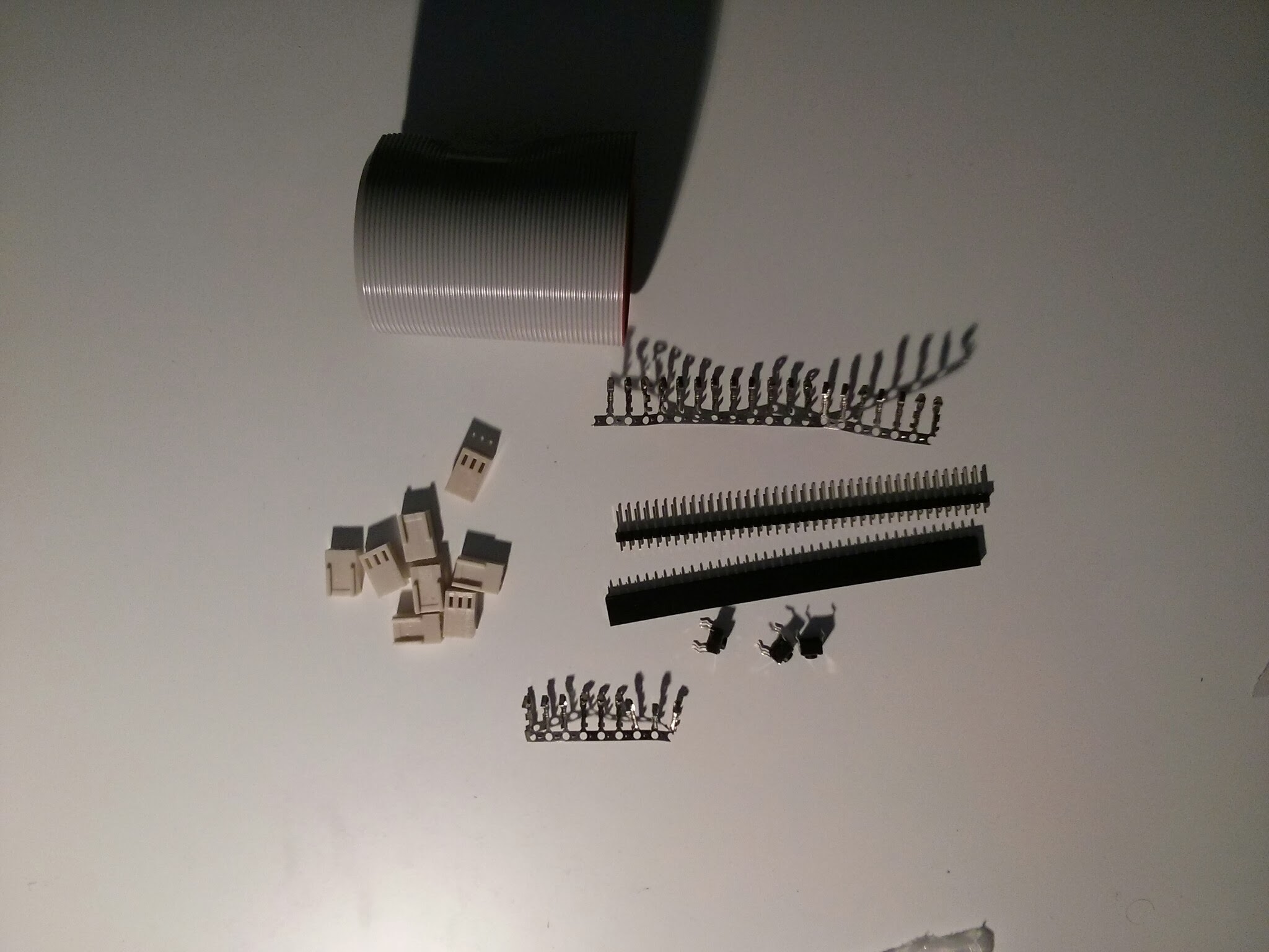
– Some ribbon cable
– 3 buttons the same type as in the HxC
– some connectors as you can see in the picture, in order to fit the screen (dont know the exact names, the pic should be self explaining)
– a rectangular piece of solder board (mine is 8cm x 5cm, not shown in this picture)
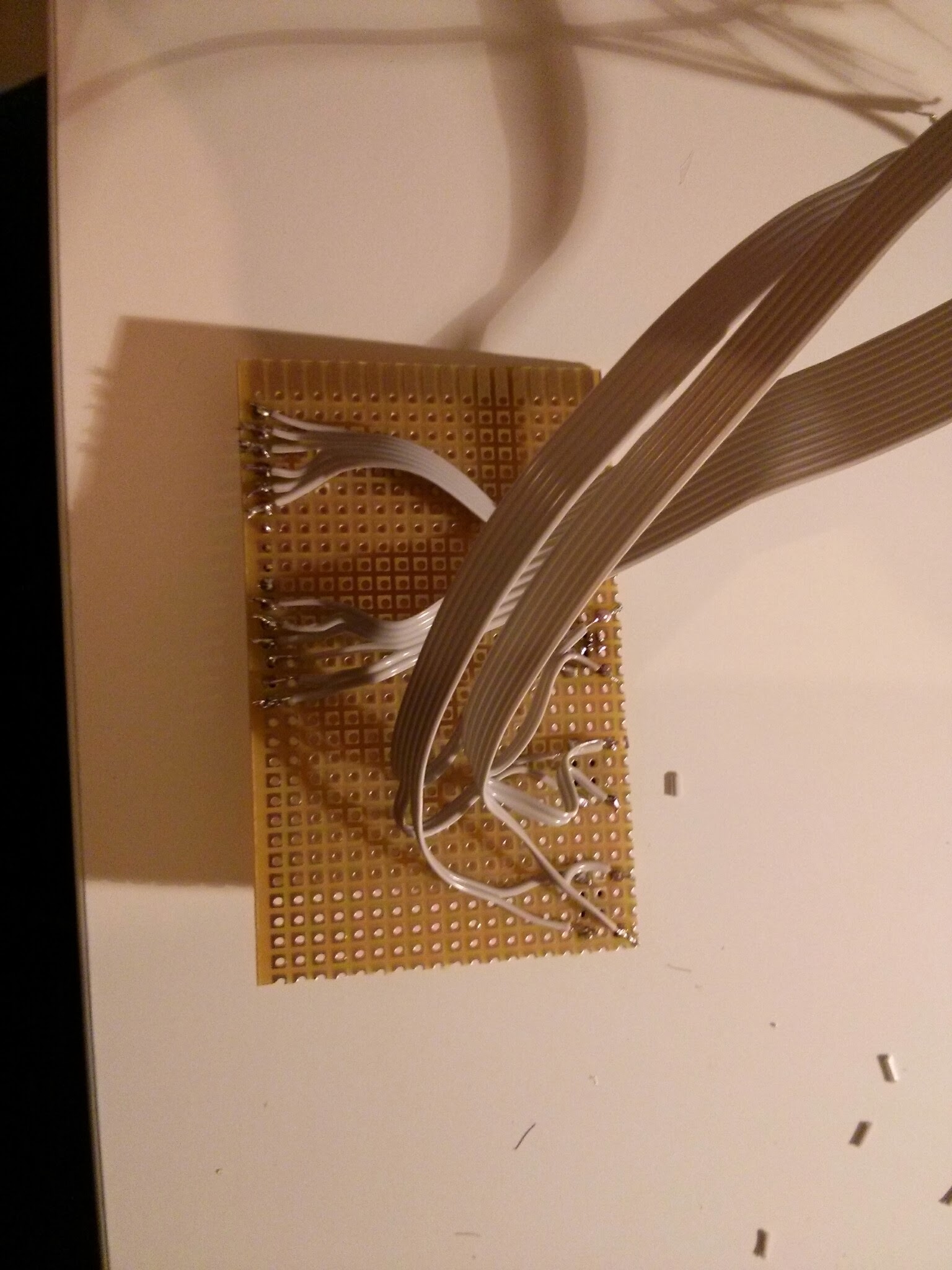
When you have all the parts needed, detach the screen from the main board

then create the daughterboard

put the screen connector on top and at the bottom the three buttons.
Then solder a 6-ribbon cable to the top ends of the buttons, and another 6-ribbon cable to the bottom ends of the buttons

finally solder a 12-ribbon cable to the screen connectors.
The final result should be something like this:
That’s it with the daughterboard, lets move to the main board.
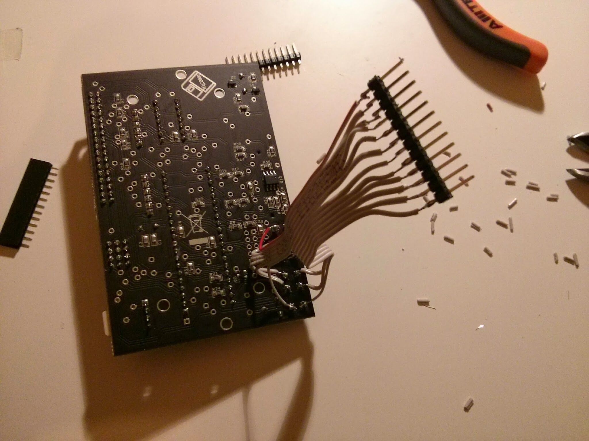
Pass the 3 ribbons through the amiga case ventilation holes on top of the “Amiga” logo. I advise you to remove the keyboard ribbon for your convenience.
get a 12-ribbon cable and solder it to the ends of the buttons as in the picture. The left 6 are for the top button ends, the right 6 for the bottom ends
Solder the female black connector to the daughterboard’s button’s ribbons, take care to solder the wires in the same order as they are in the picture above.
Connect the 12-ribbon cable from the daughterboard’s screen connector to the mainboard’s screen connector keeping the correct order. I used these white 3-hole connectors to make it detachable. Something like in this picture:

Then all connections should be connected, make a check to see if everything is ok, and place the mainboard as close as the floppy’s entrance is in the amiga’s case, in order to be able to take out and place in the sd card. Notice I put some insulation on the back of the mainboard in order not to make any short circuit with the amiga’s motherboard.

Connect the floppy cable, the power cable (dont forget the keyboard cable) and put the case back.
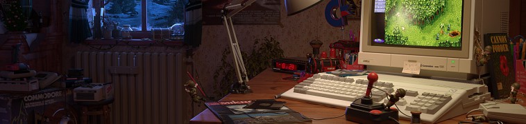
The final result should be something like this:
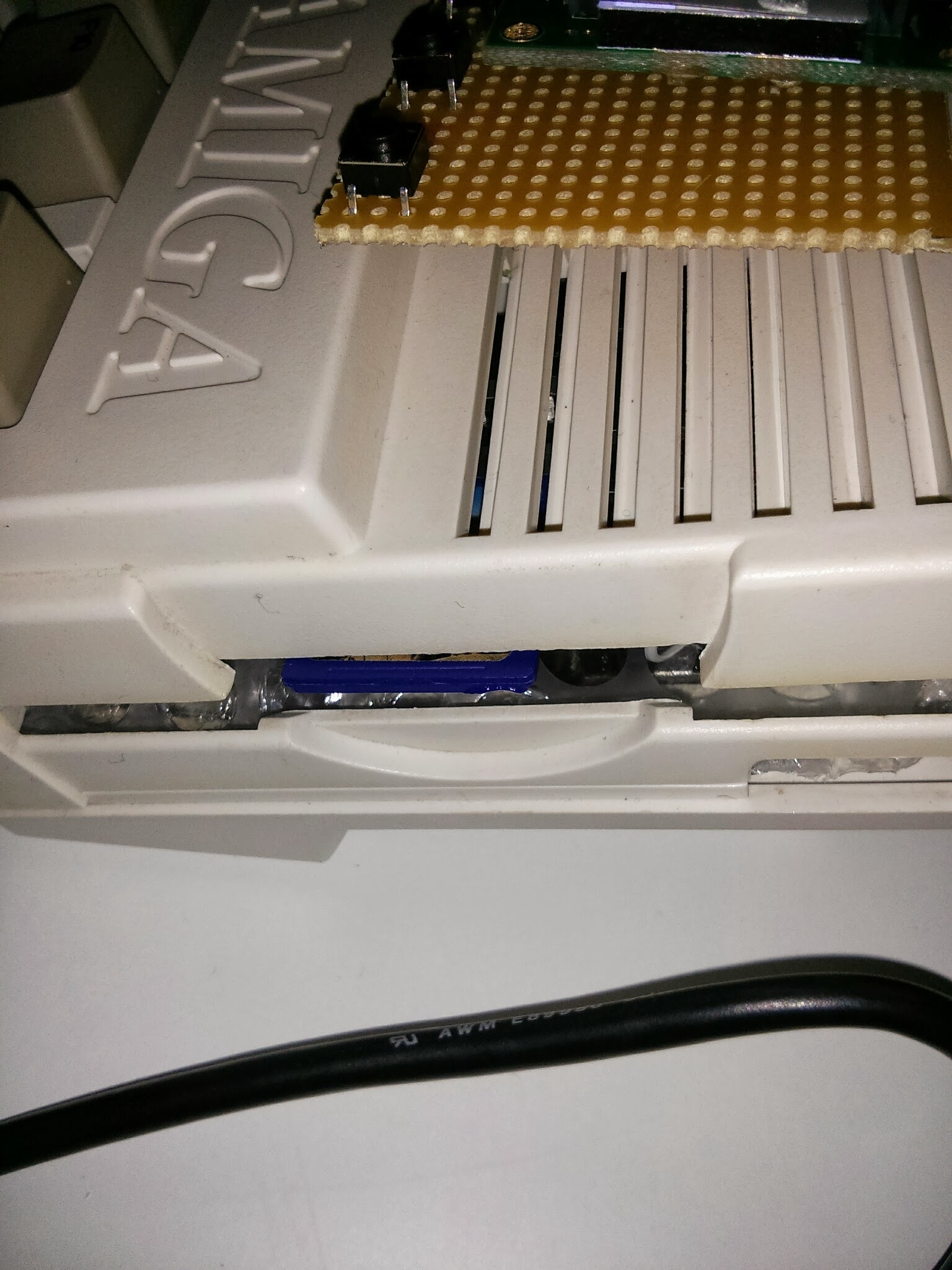
(the blue sd card shows through the floppy hole)

(the daughterboard with the screen and it’s buttons)
some more pictures:


